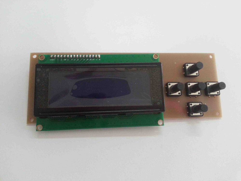
Melzi V2.0 with LCD2004 and 5 keys
Hello there,
about 4 weeks ago I bought my first 3D printer. Through a silly mishap I shot up my first Melzi Board. I had requested the firmware by the seller, but unfortunately he is not willing to cooperate with me.
My self-configured "firmware" is now already at a good level, but I do not get to run the display.
Here is my hardware configuration as it has already worked with the firmware from the delivery status.
RepRap Melzi V2.0
With this one LCD.... LCD2004A
Pin connections:
The 5 Keys are connected at Analog Input Pin 36
I hope someone can help me with the configuration.
Thank You!
Jan
about 4 weeks ago I bought my first 3D printer. Through a silly mishap I shot up my first Melzi Board. I had requested the firmware by the seller, but unfortunately he is not willing to cooperate with me.
My self-configured "firmware" is now already at a good level, but I do not get to run the display.
Here is my hardware configuration as it has already worked with the firmware from the delivery status.
RepRap Melzi V2.0
With this one LCD.... LCD2004A
Pin connections:
|
Display |
Atmega1284P |
|
E |
35 |
|
RS |
34 |
|
D4 |
11 |
|
D5 |
12 |
|
D6 |
19 |
|
D7 |
20 |
The 5 Keys are connected at Analog Input Pin 36
|
Key |
Resistor |
|
UP |
3,2 kO |
|
LEFT |
2,8 kO |
|
RIGHT |
3,3 kO |
|
DOWN |
2,9 kO |
|
MIDDLE |
3,0 kO |
|
No Key pushed |
4,7 kO |
I hope someone can help me with the configuration.
Thank You!
Jan
Comments
but it worked already with this keys....
Which display you would recommend to the Board?
I would not buy one that is not working with the Board.
Thank you very much!
Unfortunately, my display is still not working.
But I have taken a first step to test the display at all.
With the Liquid Crystal Library for Arduino it works.
Here's the code (It's the example Code from Arduino):
// include the library code:
#include <LiquidCrystal.h>
// initialize the library with the numbers of the interface pins
// RS, E, D4, D5, D6, D7
LiquidCrystal lcd(28, 29, 10, 11, 16, 17);
void setup()
{
// set up the LCD's number of columns and rows:
lcd.begin(20, 4);
// Print a message to the LCD.
lcd.print("hello, world!");
}
void loop()
{
}
In configuration.h i have put it on 1
#define FEATURE_CONTROLLER 1
And here is the code from the firmware.
uiconfig.h
This file is part of Repetier-Firmware.
Repetier-Firmware is free software: you can redistribute it and/or modify
it under the terms of the GNU General Public License as published by
the Free Software Foundation, either version 3 of the License, or
(at your option) any later version.
Repetier-Firmware is distributed in the hope that it will be useful,
but WITHOUT ANY WARRANTY; without even the implied warranty of
MERCHANTABILITY or FITNESS FOR A PARTICULAR PURPOSE. See the
GNU General Public License for more details.
You should have received a copy of the GNU General Public License
along with Repetier-Firmware. If not, see <http://www.gnu.org/licenses/>.
*/
/* ===================== IMPORTANT ========================
The LCD and Key support is new. I tested everything as good as possible,
but some combinations may not work as supposed.
The I2C methods rely on a stable I2C connection. Noise may cause wrong signals
which can cause the firmware to freeze.
The ui adds quite some code, so AVRs with 64kB ram (Sanguino, Gen6) can not handle all features
of the firmware at the same time. You have to disable some features to gain the
ram needed. What should work:
- No sd card - the sd card code is quite large.
- No keys attached - The longest part is the menu handling.
- EEPROM_MODE 0 .
Currently supported hardware:
*** Displays ***
- direct connected lcd with 4 data lines
- connected via i2c
*** Keys ***
- rotary encoder
- push button
- key matrix up to 4x4
- rotary encoder via i2c (only slow turns are captured correct)
- push button via i2c
*** Buzzer ***
- directly connected, high = on
- connected via i2c, low = on
==============================================================*/
#ifndef _ui_config_h
#define _ui_config_h
/** While the ascii chars are all the same, the driver have different charsets
for special chars used in different countries. The charset allows to fix for
this problem. If characters look wrong, try a different charset. If nothing
works, use the ascii charset 0 as fallback. Not the nicest for everything but working!
0 = ASCII fallback
1 = Default works on most displays. This has some japanese chars in charset
2 = Alternative charset with more european chars
*/
#define UI_DISPLAY_CHARSET 1
/** Select type of beeper
0 = none
1 = Piezo connected to pin
2 = Piezo connected to a pin over I2C
*/
#ifndef BEEPER_TYPE
#define BEEPER_TYPE 0
#define BEEPER_TYPE_INVERTING false
#endif
#if BEEPER_TYPE==1 && !defined(BEEPER_PIN)
#define BEEPER_PIN 37
#endif
#if BEEPER_TYPE==2
#define BEEPER_ADDRESS 0x40 // I2C address of the chip with the beeper pin
#define BEEPER_PIN _BV(7) // Bit value for pin 8
#define COMPILE_I2C_DRIVER // We need the I2C driver as we are using i2c
#endif
/**
What display type do you use?
0 = No display - do not use here. Set FEATURE_CONTROLLER 0 instead
1 = LCD Display with 4 bit data bus
2 = LCD Display with 8 bit data bus (currently not implemented, fallback to 1)
3 = LCD Display with I2C connection, 4 bit mode
4 = Use the slower LiquiedCrystal library bundled with arduino.
IMPORTANT: You need to uncomment the LiquidCrystal include in Repetier.pde for it to work.
If you have Sanguino and want to use the library, you need to have Arduino 023 or older. (13.04.2012)
5 = U8G supported display
*/
#define UI_DISPLAY_TYPE 1
#if UI_DISPLAY_TYPE == DISPLAY_U8G // Special case for graphic displays
// You need to define which controller you use and set pins accodringly
// For software spi assign these definitions
// SCK Pin: UI_DISPLAY_D4_PIN
// Mosi Pin: UI_DISPLAY_ENABLE_PIN
// CD Pin: UI_DISPLAY_RS_PIN
// ST7920 with software SPI
#define U8GLIB_ST7920
// SSD1306 with software SPI
//#define U8GLIB_SSD1306_SW_SPI
// SSD1306 over I2C using hardware I2C pins
//#define U8GLIB_SSD1306_I2C
// For the 8 bit ks0108 display you need to set these pins
// UI_DISPLAY_D0_PIN,UI_DISPLAY_D1_PIN,UI_DISPLAY_D2_PIN,UI_DISPLAY_D3_PIN,UI_DISPLAY_D4_PIN,UI_DISPLAY_D5_PIN,UI_DISPLAY_D6_PIN,UI_DISPLAY_D7_PIN
// UI_DISPLAY_ENABLE_PIN,UI_DISPLAY_CS1,UI_DISPLAY_CS2,
// UI_DISPLAY_DI,UI_DISPLAY_RW_PIN,UI_DISPLAY_RESET_PIN
//#define U8GLIB_KS0108
//#define U8GLIB_KS0108_FAST
// UI_DISPLAY_RS_PIN = CS
// UI_DISPLAY_D5_PIN = A0
//#define U8GLIB_ST7565_NHD_C2832_HW_SPI
#define UI_LCD_WIDTH 128
#define UI_LCD_HEIGHT 64
//select font size
#define UI_FONT_6X10 //default font
#ifdef UI_FONT_6X10
#define UI_FONT_WIDTH 6
#define UI_FONT_HEIGHT 10
#define UI_FONT_SMALL_HEIGHT 7
#define UI_FONT_DEFAULT repetier_6x10
#define UI_FONT_SMALL repetier_5x7
#define UI_FONT_SMALL_WIDTH 5 //smaller font for status display
#define UI_ANIMATION false // Animations are too slow
#endif
//calculate rows and cols available with current font
#define UI_COLS (UI_LCD_WIDTH/UI_FONT_WIDTH)
#define UI_ROWS (UI_LCD_HEIGHT/UI_FONT_HEIGHT)
#define UI_DISPLAY_CHARSET 3
#else
/** Number of columns per row
Typical values are 16 and 20
*/
#define UI_COLS 20
/**
Rows of your display. 2 or 4
*/
#define UI_ROWS 4
#endif // UI_DISPLAY_TYPE
/* What type of chip is used for I2C communication
0 : PCF8574 or PCF8574A or compatible chips.
1 : MCP23017
*/
#define UI_DISPLAY_I2C_CHIPTYPE 0
// 0x40 till 0x4e for PCF8574, 0x40 for the adafruid RGB shield, 0x40 - 0x4e for MCP23017
// Official addresses have a value half as high!
#define UI_DISPLAY_I2C_ADDRESS 0x4e
// For MCP 23017 define which pins should be output
#define UI_DISPLAY_I2C_OUTPUT_PINS 65504
// Set the output mask that is or'd over the output data. This is needed to activate
// a backlight switched over the I2C.
// The adafruit RGB shields enables a light if the bit is not set. Bits 6-8 are used for backlight.
#define UI_DISPLAY_I2C_OUTPUT_START_MASK 0
// For MCP which inputs are with pullup. 31 = pins 0-4 for adafruid rgb shield buttons
#define UI_DISPLAY_I2C_PULLUP 31
/* How fast should the I2C clock go. The PCF8574 work only with the lowest setting 100000.
A MCP23017 can run also with 400000 Hz */
#define UI_I2C_CLOCKSPEED 100000L
/**
Define the pin
*/
#if UI_DISPLAY_TYPE == DISPLAY_I2C // I2C Pin configuration
#define UI_DISPLAY_RS_PIN _BV(4)
#define UI_DISPLAY_RW_PIN _BV(5)
#define UI_DISPLAY_ENABLE_PIN _BV(6)
#define UI_DISPLAY_D0_PIN _BV(0)
#define UI_DISPLAY_D1_PIN _BV(1)
#define UI_DISPLAY_D2_PIN _BV(2)
#define UI_DISPLAY_D3_PIN _BV(3)
#define UI_DISPLAY_D4_PIN _BV(0)
#define UI_DISPLAY_D5_PIN _BV(1)
#define UI_DISPLAY_D6_PIN _BV(2)
#define UI_DISPLAY_D7_PIN _BV(3)
// uncomment if your using led to indicated the bed is hot
//#define UI_I2C_HEATBED_LED _BV(8)
// uncomment if your using led to indicated the extruder is hot
//#define UI_I2C_HOTEND_LED _BV(7)
// uncomment if your using led to indicated the FAN is on
//#define UI_I2C_FAN_LED _BV(6)
// Pins for adafruid RGB shield
/*#define UI_DISPLAY_RS_PIN _BV(15)
#define UI_DISPLAY_RW_PIN _BV(14)
#define UI_DISPLAY_ENABLE_PIN _BV(13)
#define UI_DISPLAY_D0_PIN _BV(12)
#define UI_DISPLAY_D1_PIN _BV(11)
#define UI_DISPLAY_D2_PIN _BV(10)
#define UI_DISPLAY_D3_PIN _BV(9)
#define UI_DISPLAY_D4_PIN _BV(12)
#define UI_DISPLAY_D5_PIN _BV(11)
#define UI_DISPLAY_D6_PIN _BV(10)
#define UI_DISPLAY_D7_PIN _BV(9)*/
#else // Direct display connections
#define UI_DISPLAY_RS_PIN 28 // PINK.1, 88, D_RS
#define UI_DISPLAY_RW_PIN -1
#define UI_DISPLAY_ENABLE_PIN 29 // PINK.3, 86, D_E
#define UI_DISPLAY_D0_PIN -1 // PINF.5, 92, D_D4
#define UI_DISPLAY_D1_PIN -1 // PINK.2, 87, D_D5
#define UI_DISPLAY_D2_PIN -1 // PINL.5, 40, D_D6
#define UI_DISPLAY_D3_PIN -1 // PINK.4, 85, D_D7
#define UI_DISPLAY_D4_PIN 10 // PINF.5, 92, D_D4
#define UI_DISPLAY_D5_PIN 11 // PINK.2, 87, D_D5
#define UI_DISPLAY_D6_PIN 16 // PINL.5, 40, D_D6
#define UI_DISPLAY_D7_PIN 17 // PINK.4, 85, D_D7
#define UI_DELAYPERCHAR 50
// Special pins for some u8g driven display
#define UI_DISPLAY_CS1 -1
#define UI_DISPLAY_CS2 -1
#define UI_DISPLAY_DI -1
#define UI_DISPLAY_RW_PIN -1
#define UI_DISPLAY_RESET_PIN -1
#endif
/** \brief Are some keys connected?
0 = No keys attached - disables also menu
1 = Some keys attached
*/
#define UI_HAS_KEYS 0
/** \brief Is a back key present.
If you have menus enabled, you need a method to leave it. If you have a back key, you can always go one level higher.
Without a back key, you need to navigate to the back entry in the menu. Setting this value to 1 removes the back entry.
*/
#define UI_HAS_BACK_KEY 1
/* Then you have the next/previous keys more like up/down keys, it may be more intuitive to change the direction you skip through the menus.
If you set it to true, next will go to previous menu instead of the next menu.
*/
#define UI_INVERT_MENU_DIRECTION 0
/** Uncomment this, if you have keys connected via i2c to a PCF8574 chip. */
//#define UI_HAS_I2C_KEYS
// Do you have a I2C connected encoder?
#define UI_HAS_I2C_ENCODER 0
// Under which address can the key status requested. This is the address of your PCF8574 where the keys are connected.
// If you use a MCP23017 the address from display is used also for keys.
#define UI_I2C_KEY_ADDRESS 0x40
#ifdef UI_MAIN
/* #######################################################################
Key definitions
The firmware is very flexible regarding your input methods. You can use one
or more of the predefined key macros, to define a mapper. If no matching mapper
is available, you can add you c-code for mapping directly into the keyboard
routines. The predefined macros do the same, just hiding the code behind it.
For each key, two seperate parts must be defined. The first is the initialization
which must be added inside uiInitKeys() and the second ist a testing routine.
These come into uiCheckKeys() or uiCheckSlowKeys() depending on the time needed
for testing. If you are in doubt, put it in uiCheckSlowKeys().
uiInitKeys() is called from an interrupt controlling the extruder, so only
fast tests should be put there.
The detect methods need an action identifier. A list of supported ids is found
at the beginning of ui.h It's best to use the symbol name, in case the value changes.
1. Simple push button connected to gnd if closed on a free arduino pin
init -> UI_KEYS_INIT_BUTTON_LOW(pinNumber);
detect -> UI_KEYS_BUTTON_LOW(pinNumber,action);
2. Simple push button connected to 5v if closed on a free arduino pin
init -> UI_KEYS_INIT_BUTTON_HIGH(pinNumber);
detect -> UI_KEYS_BUTTON_HIGH(pinNumber,action);
3. Click encoder, A/B connected to gnd if closed.
init -> UI_KEYS_INIT_CLICKENCODER_LOW(pinA,pinB);
detect -> UI_KEYS_CLICKENCODER_LOW(pinA,pinB);
or UI_KEYS_CLICKENCODER_LOW_REV(pinA,pinB); // reverse direction
If you can move the menu cursor without a click, just be adding some force in one direction,
toggle the _REV with non _REV and toggle pins.
If the direction is wrong, toggle _REV with non _REV version.
For the push button of the encoder use 1.
4. Click encoder, A/B connected to 5V if closed.
init -> UI_KEYS_INIT_CLICKENCODER_HIGH(pinA,pinB);
detect -> UI_KEYS_CLICKENCODER_HIGH(pinA,pinB);
or UI_KEYS_CLICKENCODER_HIGH_REV(pinA,pinB); // reverse direction
If you can move the menu cursor without a click, just be adding some force in one direction,
toggle the _REV with non _REV and toggle pins.
If the direction is wrong, toggle _REV with non _REV version.
For the push button of the encoder use 2.
5. Maxtrix keyboard with 1-4 rows and 1-4 columns.
init -> UI_KEYS_INIT_MATRIX(r1,r2,r3,r4,c1,c2,c3,c4);
detect -> UI_KEYS_MATRIX(r1,r2,r3,r4,c1,c2,c3,c4);
In addition you have to set UI_MATRIX_ACTIONS to match your desired actions.
------- Keys connected via I2C -------------
All keys and the buzzer if present must be on a connected to a single PCF8574 chip!
As all I2C request take time, they belong all in uiCheckSlowKeys.
Dont use the pin ids but instead _BV(pinNumber0_7) as pin id. 0 = First pin
6. Click encoder, A/B connected to gnd if closed.
init -> not needed, but make sure UI_HAS_I2C_KEY is not commented out.
detect -> UI_KEYS_I2C_CLICKENCODER_LOW(pinA,pinB);
or UI_KEYS_I2C_CLICKENCODER_LOW_REV(pinA,pinB); // reverse direction
If you can move the menu cursor without a click, just be adding some force in one direction,
toggle the _REV with non _REV and toggle pins.
If the direction is wrong, toggle _REV with non _REV version.
For the push button of the encoder use 7.
NOTICE: The polling frequency is limited, so only slow turns are captured correct!
7. Simple push button connected to gnd if closed via I2C on a PCF8574
init -> not needed, but make sure UI_HAS_I2C_KEY is not commented out.
detect -> UI_KEYS_I2C_BUTTON_LOW(pinNumber,action);
-------- Some notes on actions -------------
There are three kinds of actions.
Type 1: Immediate actions - these are execute and forget actions like home/pre-heat
Type 2: Parameter change action - these change the mode for next/previous keys. They are valid
until a new change action is initiated or the action is finished with ok button.
Type 3: Show menu action. These actions have a _MENU_ in their name. If they are executed, a new
menu is pushed on the menu stack and you see the menu. If you assign these actions directly
to a key, you might not want this pushing behaviour. In this case add UI_ACTION_TOPMENU to the
action, like UI_ACTION_TOPMENU+UI_ACTION_MENU_XPOSFAST. That will show the menu as top-menu
closing all othe submenus that were open.
####################################################################### */
// Use these codes for key detect. The main menu will show the pressed action in the lcd display.
// after that assign the desired codes.
//#define UI_MATRIX_ACTIONS {2000,2001,2002,2003,2004,2005,2006,2007,2008,2009,2010,2011,2012,2013,2014,2015}
// Define your matrix actions
#define UI_MATRIX_ACTIONS {UI_ACTION_HOME_ALL, UI_ACTION_TOP_MENU, UI_ACTION_SET_ORIGIN, UI_ACTION_NEXT,\
UI_ACTION_HOME_Z, UI_ACTION_MENU_ZPOS, UI_ACTION_COOLDOWN, UI_ACTION_OK,\
UI_ACTION_HOME_Y, UI_ACTION_MENU_YPOSFAST, UI_ACTION_PREHEAT_ABS, UI_ACTION_PREVIOUS,\
UI_ACTION_HOME_X, UI_ACTION_MENU_XPOSFAST, UI_ACTION_DISABLE_STEPPER, UI_ACTION_BACK}
#ifdef UI_MATRIX_ACTIONS
const int matrixActions[] PROGMEM = UI_MATRIX_ACTIONS;
#endif
void uiInitKeys() {
#if UI_HAS_KEYS!=0
//UI_KEYS_INIT_CLICKENCODER_LOW(33,31); // click encoder on pins 47 and 45. Phase is connected with gnd for signals.
UI_KEYS_INIT_BUTTON_LOW(4); // push button, connects gnd to pin
UI_KEYS_INIT_BUTTON_LOW(5);
UI_KEYS_INIT_BUTTON_LOW(6);
UI_KEYS_INIT_BUTTON_LOW(11);
UI_KEYS_INIT_BUTTON_LOW(42);
// UI_KEYS_INIT_CLICKENCODER_LOW(47,45); // click encoder on pins 47 and 45. Phase is connected with gnd for signals.
// UI_KEYS_INIT_BUTTON_LOW(43); // push button, connects gnd to pin
// UI_KEYS_INIT_MATRIX(32,47,45,43,41,39,37,35);
#endif
}
void uiCheckKeys(int &action) {
#if UI_HAS_KEYS!=0
//UI_KEYS_CLICKENCODER_LOW_REV(33,31); // click encoder on pins 47 and 45. Phase is connected with gnd for signals.
UI_KEYS_BUTTON_LOW(4,UI_ACTION_OK); // push button, connects gnd to pin
UI_KEYS_BUTTON_LOW(5,UI_ACTION_NEXT); // push button, connects gnd to pin
UI_KEYS_BUTTON_LOW(6,UI_ACTION_PREVIOUS); // push button, connects gnd to pin
UI_KEYS_BUTTON_LOW(11,UI_ACTION_BACK); // push button, connects gnd to pin
UI_KEYS_BUTTON_LOW(42,UI_ACTION_SD_PRINT ); // push button, connects gnd to pin
// UI_KEYS_CLICKENCODER_LOW_REV(47,45); // click encoder on pins 47 and 45. Phase is connected with gnd for signals.
// UI_KEYS_BUTTON_LOW(43,UI_ACTION_OK); // push button, connects gnd to pin
#endif
}
inline void uiCheckSlowEncoder() {
#if defined(UI_HAS_I2C_KEYS) && UI_HAS_KEYS!=0
#if UI_DISPLAY_I2C_CHIPTYPE==0
HAL::i2cStartWait(UI_I2C_KEY_ADDRESS+I2C_READ);
uint8_t keymask = HAL::i2cReadNak(); // Read current key mask
#endif
#if UI_DISPLAY_I2C_CHIPTYPE==1
HAL::i2cStartWait(UI_DISPLAY_I2C_ADDRESS+I2C_WRITE);
HAL::i2cWrite(0x12); // GIOA
HAL::i2cStop();
HAL::i2cStartWait(UI_DISPLAY_I2C_ADDRESS+I2C_READ);
unsigned int keymask = HAL::i2cReadAck();
keymask = keymask + (HAL::i2cReadNak()<<8);
#endif
HAL::i2cStop();
// Add I2C click encoder tests here, all other i2c tests and a copy of the encoder test belog in uiCheckSlowKeys
UI_KEYS_I2C_CLICKENCODER_LOW_REV(_BV(2),_BV(0)); // click encoder on pins 0 and 2. Phase is connected with gnd for signals.
#endif
}
void uiCheckSlowKeys(int &action) {
#if defined(UI_HAS_I2C_KEYS) && UI_HAS_KEYS!=0
#if UI_DISPLAY_I2C_CHIPTYPE==0
HAL::i2cStartWait(UI_I2C_KEY_ADDRESS+I2C_READ);
uint8_t keymask = HAL::i2cReadNak(); // Read current key mask
#endif
#if UI_DISPLAY_I2C_CHIPTYPE==1
HAL::i2cStartWait(UI_DISPLAY_I2C_ADDRESS+I2C_WRITE);
HAL::i2cWrite(0x12); // GPIOA
HAL::i2cStop();
HAL::i2cStartWait(UI_DISPLAY_I2C_ADDRESS+I2C_READ);
unsigned int keymask = HAL::i2cReadAck();
keymask = keymask + (HAL::i2cReadNak()<<8);
#endif
HAL::i2cStop();
// Add I2C key tests here
UI_KEYS_I2C_CLICKENCODER_LOW_REV(_BV(2),_BV(0)); // click encoder on pins 0 and 2. Phase is connected with gnd for signals.
UI_KEYS_I2C_BUTTON_LOW(_BV(1),UI_ACTION_OK); // push button, connects gnd to pin
UI_KEYS_I2C_BUTTON_LOW(_BV(3),UI_ACTION_BACK); // push button, connects gnd to pin
UI_KEYS_I2C_BUTTON_LOW(_BV(4),UI_ACTION_MENU_QUICKSETTINGS+UI_ACTION_TOPMENU); // push button, connects gnd to pin
UI_KEYS_I2C_BUTTON_LOW(_BV(5),UI_ACTION_MENU_EXTRUDER+UI_ACTION_TOPMENU); // push button, connects gnd to pin
UI_KEYS_I2C_BUTTON_LOW(_BV(6),UI_ACTION_MENU_POSITIONS+UI_ACTION_TOPMENU); // push button, connects gnd to pin
/*
// Button handling for the Adafruit RGB shild
UI_KEYS_I2C_BUTTON_LOW(4,UI_ACTION_PREVIOUS); // Up button
UI_KEYS_I2C_BUTTON_LOW(8,UI_ACTION_NEXT); // down button
UI_KEYS_I2C_BUTTON_LOW(16,UI_ACTION_BACK); // left button
UI_KEYS_I2C_BUTTON_LOW(2,UI_ACTION_OK); // right button
UI_KEYS_I2C_BUTTON_LOW(1,UI_ACTION_MENU_QUICKSETTINGS); //Select button
// ----- End RGB shield ----------
*/
#endif
//UI_KEYS_MATRIX(32,47,45,43,41,39,37,35);
}
#endif
#endif
I hope you can say me whats wrong....
I bought a Prusa I3 with the same lcd & kb like you (this one : http://www.aliexpress.com/item/Black-Factory-High-Quality-Precision-Reprap-Prusa-i3-DIY-3d-Printer-kit-with-2-Rolls-Filament/32357171936.html )
The vendor is very nice, he has sent me the firmware I asked him because I want to add an inductive sensor for auto-leveling.
If you want, I can send it to you by email.
Will send a private with my mail, would l please send the firmware?
Since I have email requests for the source code , I must add that I have examined it in the meantime.
I can compile it with Arduino 1.04 but it does NOT contain the code to read the 5 key board: there must be an AnalogRead somewhere but I can't find it. So the seller must have sent me a generic Repetier code without the customization for his board. The hex code in the zip seems good though since I can find the string "Omni v1.4", same as displayed on the LCD.
So my auto-leveling mod is not possible for the moment and pending.
It would be great if you all ask the vendor to release the real source code and write in AliExpress feedback to dissuade prospective buyers to buy the Hesine printer to pressure the vendor to comply.
Hello,
and thank you all for adapting the firmware!
I have a simple question:
Under "mechanics"-->"stepper" both (x and y axis stepper) have the value 85.333 instead of the standard value 80.000. Can anybody explain me the reason for this?
Thank you and regards
Matthias
Edit, ok, after reading this it's more clear to me: https://www.matterhackers.com/news/3d-printer-firmware-settings-stepper-motor-configuration
" For belt driven axes (usually x and y), the steps per unit is determined by the number of steps per revolution divided by the idler teeth, divided by the belt pitch (ie the spacing between teeth)"
So I hope this was not a "guessed" value (perhaps via "try and error") by the original author...
great work every one you've really helped me out!