Confusing results with G33 and Bed Height Map tool for a Delta printer

So I'm calibrating my Delta printer and the initial bed height map was something like this:
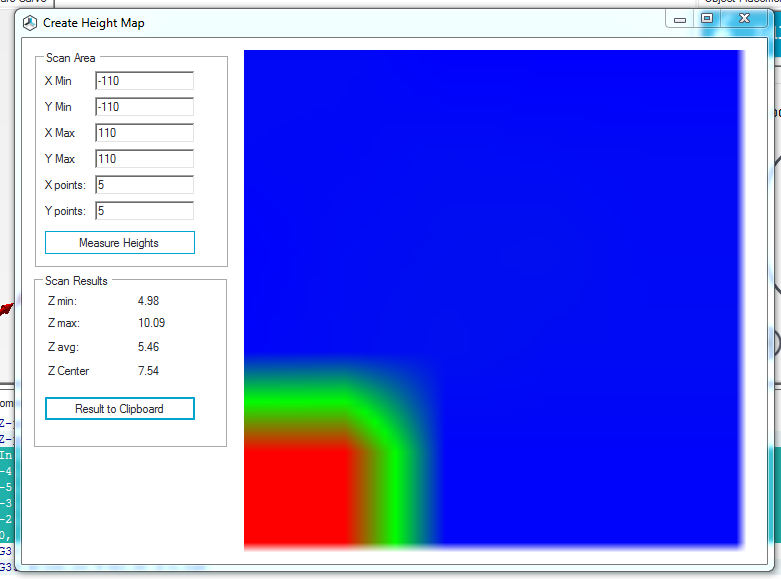
X:	-110.00	-55.00	0.00	55.00	110.00
y: 110.00 5.07 5.07 4.99 4.98 4.98
y: 55.00 5.06 5.05 5.09 5.07 5.06
y: 0.00 5.00 5.08 5.11 5.13 5.07
y: -55.00 5.03 5.09 5.13 5.09 5.09
y: -110.00 10.09 10.08 5.03 5.03 5.03

The red spot at one corner itself was very confusing but I went ahead with G33 to see what it does.


This is the correction matrix I got from G33:

22:07:11.681 : Info:Distortion correction matrix:
22:07:11.681 : -4, -5, -7, 2, 13
22:07:11.681 : -5, -9, -10, -11, -6
22:07:11.681 : -3, -10, -13, -15, -9
22:07:11.681 : -2, -10, -13, -13, -3
22:07:11.681 : 0, -6, -8, -3, 13


Then, I ran the Bed Height Map tool again to see what G33 had done. Here are the results:
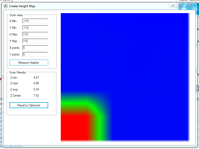

X:	-110.00	-55.00	0.00	55.00	110.00
y: 110.00 4.93 4.93 4.88 4.88 4.87
y: 55.00 4.94 4.94 4.96 4.92 4.93
y: 0.00 4.96 4.95 4.94 4.92 4.95
y: -55.00 4.94 4.96 4.96 4.95 4.95
y: -110.00 9.96 9.96 4.94 4.94 4.94


I don't understand whats going on. What is that red spot and why did it not go away? Also, why are two values in the height map close to 10 while the others are close to 5? I started the bed height map tool at z=5.

Comments

  • You have set max. zprpobe bed distance to 5 in firmware. Starting higher results in a good value for that point and then the correct height gets enforced. So solution is either to increase that value or start measuring at 4mm.
  • My Z_PROBE_BED_DISTANCE was set to 10. I started the "Bed Height Map" tool at Z=10 and that cleared the confusion.

    However, I still have a few queries.
    Here are my distortion correction values:
    #define DISTORTION_CORRECTION 1
    #define DISTORTION_CORRECTION_POINTS 5
    #define DISTORTION_CORRECTION_R 100
    #define DISTORTION_PERMANENT 1
    #define DISTORTION_UPDATE_FREQUENCY 15
    #define DISTORTION_START_DEGRADE 0.5
    #define DISTORTION_END_HEIGHT 1
    #define DISTORTION_EXTRAPOLATE_CORNERS 0
    #define DISTORTION_XMIN 10
    #define DISTORTION_YMIN 10
    #define DISTORTION_XMAX 190
    #define DISTORTION_YMAX 190

    Here the radius is 100. But when I keep the same radius for Bed Height Map tool (XMax and Ymax to 100, XMin and YMin to -100) it uses different points. This might sound really odd, but when I watch the points used by G33 and Bed Height Map tool, I can clearly see that they are different. Why is it so?


  • Sure it uses different points. See G33 L0 output to see used coordinates. The order of measurement will surely differ as these are different methods, but it should use the same position as both activate the z probe offset.
  • edited September 2017
    Actually G33 is using a proper 5x5 point matrix whereas the Bed Height Map tool isn't using the four corner points. So (-100,-100), (100,-100), (100,100) and (-100,100) are not being measured by the Bed Height Map tool. Shouldn't it be the reverse? If G33 uses a radius, then the corner points would be at a distance of 141.42mm from the center so they should be invalid as per radius=100. But rather the Bed Height Map tool, which uses max and min values for x and y, is not measuring the corner points. Why is this happening?
  • G33 omits edges if you have compiled it with the flag set.
    Hosts does always measure a rectangular area, see send commands. What might happen is that printer refused to move there due to some constraint being hit and it just measured instead where it was.
  • edited September 2017
    Repetier said:
    G33 omits edges if you have compiled it with the flag set.
    Can you please explain? I have mentioned my distortion parameters in an earlier comment. Moreover G33 isn't omitting anything, it is measuring all points of a 5x5 matrix between -100 and 100 in both X and Y directions.

    This is the log following Bed Height Map tool. I can see G1 commands with the corner coordinates, but for some reason, no Z-probe was executed at those points (-100,-100), (100,-100), (100,100), (-100,-100).
    18:11:32.244 : N48 G1 X-100 Y-100 Z10 F4800*4
    18:11:32.244 : N49 G30 P1*102
    18:11:32.244 : N50 G1 X-50 Y-100 Z10 F4800*57
    18:11:32.244 : N51 G30 P0*110
    18:11:32.244 : N52 G1 X0 Y-100 Z10 F4800*35
    18:11:32.244 : N53 G30 P0*108
    18:11:32.244 : N54 G1 X50 Y-100 Z10 F4800*16
    18:11:32.268 : X:0.00 Y:-0.00 Z:10.000 E:0.0000
    18:11:32.268 : Info:Autoleveling disabled
    18:11:32.268 : N55 G30 P0*106
    18:11:48.996 : SelectExtruder:0
    18:11:49.012 : X:0.00 Y:0.00 Z:310.650 E:0.0000
    18:11:49.012 : Info:Autoleveling enabled
    18:11:54.891 : Z-probe:9.90 X:-0.07 Y:0.18 zCorr:-0.11
    18:11:56.872 : N56 G1 X100.00 Y-100.00 Z10.000 F4800*56
    18:12:01.155 : Z-probe:9.83 X:-50.07 Y:-99.82 zCorr:-0.09
    18:12:03.104 : N57 G30 P0*104
    18:12:06.603 : Z-probe:9.86 X:-0.07 Y:-99.82 zCorr:-0.11
    18:12:08.568 : N58 G1 X-100.00 Y-50.00 Z10.000 F4800*47
    18:12:08.568 : N59 G30 P0*102
    18:12:12.050 : Z-probe:9.93 X:49.93 Y:-99.82 zCorr:-0.04
    18:12:14.016 : X:50.00 Y:-100.00 Z:10.003 E:0.0000
    18:12:14.016 : N60 G1 X-50.00 Y-50.00 Z10.000 F4800*16
    18:12:14.016 : N61 G30 P0*109
    18:12:16.796 : Z-probe:9.93 X:49.93 Y:-99.82 zCorr:-0.04
    18:12:18.762 : N62 G1 X0.00 Y-50.00 Z10.000 F4800*10
    18:12:18.762 : N63 G30 P0*111
    18:12:23.634 : Z-probe:9.96 X:-100.07 Y:-49.82 zCorr:-0.01
    18:12:25.615 : N64 G1 X50.00 Y-50.00 Z10.000 F4800*57
    18:12:25.615 : N65 G30 P0*105
    18:12:29.114 : Z-probe:9.97 X:-50.07 Y:-49.82 zCorr:-0.11
    18:12:31.111 : N66 G1 X100.00 Y-50.00 Z10.000 F4800*15
    18:12:31.111 : N67 G30 P0*107
    18:12:34.611 : Z-probe:9.94 X:-0.07 Y:-49.82 zCorr:-0.14
    18:12:36.592 : N68 G1 X-100.00 Y0.00 Z10.000 F4800*52
    18:12:36.592 : N69 G30 P0*101
    18:12:40.122 : Z-probe:9.98 X:49.93 Y:-49.82 zCorr:-0.14
    18:12:42.119 : N70 G1 X-50.00 Y0.00 Z10.000 F4800*9
    18:12:42.119 : N71 G30 P0*108
    18:12:42.119 : N72 G1 X0 Y0 Z10 F4800*13
    18:12:45.618 : Z-probe:10.01 X:99.93 Y:-49.82 zCorr:-0.03
    18:12:47.583 : N73 G30 P0*110
    18:12:47.583 : N74 G1 X50 Y0 Z10 F4800*62
    18:12:47.663 : N75 G30 P0*104
    18:12:53.080 : Z-probe:10.01 X:-100.07 Y:0.18 zCorr:-0.03
    18:12:55.077 : N76 G1 X100.00 Y0.00 Z10.000 F4800*22
    18:12:58.575 : Z-probe:10.01 X:-50.07 Y:0.18 zCorr:-0.10
    18:13:00.556 : N77 G30 P0*106
    18:13:04.087 : Z-probe:10.03 X:-0.07 Y:0.18 zCorr:-0.11
    18:13:06.084 : N78 G1 X-100.00 Y50.00 Z10.000 F4800*0
    18:13:06.084 : N79 G30 P0*100
    18:13:09.600 : Z-probe:9.99 X:49.93 Y:0.18 zCorr:-0.14
    18:13:11.597 : N80 G1 X-50.00 Y50.00 Z10.000 F4800*51
    18:13:11.597 : N81 G30 P0*99
    18:13:15.095 : Z-probe:10.01 X:99.93 Y:0.18 zCorr:-0.09
    18:13:17.092 : N82 G1 X0.00 Y50.00 Z10.000 F4800*41
    18:13:17.093 : N83 G30 P0*97
    18:13:22.588 : Z-probe:10.02 X:-100.07 Y:50.18 zCorr:-0.04
    18:13:24.569 : N84 G1 X50.00 Y50.00 Z10.000 F4800*26
    18:13:24.569 : N85 G30 P0*103
    18:13:28.085 : Z-probe:10.04 X:-50.07 Y:50.18 zCorr:-0.06
    18:13:30.081 : N86 G1 X100.00 Y50.00 Z10.000 F4800*44
    18:13:30.082 : N87 G30 P0*101
    18:13:33.596 : Z-probe:10.05 X:-0.07 Y:50.18 zCorr:-0.09
    18:13:35.593 : N88 G1 X-100.00 Y100.00 Z10.000 F4800*59
    18:13:35.593 : N89 G30 P0*107
    18:13:39.108 : Z-probe:10.03 X:49.93 Y:50.18 zCorr:-0.09
    18:13:41.105 : N90 G1 X-50.00 Y100.00 Z10.000 F4800*6
    18:13:41.105 : N91 G30 P0*98
    18:13:44.605 : Z-probe:9.98 X:99.93 Y:50.18 zCorr:-0.08
    18:13:46.586 : X:100.00 Y:50.00 Z:10.004 E:0.0000
    18:13:46.586 : N92 G1 X0.00 Y100.00 Z10.000 F4800*28
    18:13:46.586 : N93 G30 P0*96
    18:13:46.586 : N94 G1 X50 Y100 Z10 F4800*49
    18:13:49.397 : Z-probe:9.98 X:99.93 Y:50.18 zCorr:-0.08
    18:13:51.378 : N95 G30 P0*102
    18:13:51.378 : N96 G1 X100 Y100 Z10 F4800*7
    18:13:56.267 : Z-probe:9.99 X:-50.07 Y:100.18 zCorr:-0.11
    18:13:58.264 : N97 G30 P2*102
    18:13:58.264 : N98 M105*22
    18:13:58.596 : N99 M105*23
    18:14:01.659 : N100 M105*38
    18:14:01.780 : Z-probe:10.09 X:-0.07 Y:100.18 zCorr:-0.01
    18:14:04.716 : N101 M105*39
    18:14:07.259 : Z-probe:10.03 X:49.93 Y:100.18 zCorr:0.03
    18:14:07.770 : N102 M105*36
    18:14:09.225 : X:50.00 Y:100.00 Z:9.999 E:0.0000
    18:14:10.827 : N103 M105*37
    18:14:12.039 : Z-probe:10.06 X:49.93 Y:100.18 zCorr:0.03
    Could printer radius (max printable radius) be a constraint? Right now it is 120. I changed it to 142 in EEPROM and ran Bed Height Map tool. It did probe at one corner point, namely (100,-100) but surprisingly didn't at (-100,-100). And when it reached the third row it caused Repetier Host and the printer to freeze.
  • max. prinable radius is a contrain and remember that to issued coordinates you have to add z probe offsets to see what it will really test and which position needs to be valid. At a position like 100,100 your radius is 142 plus some offset from rotation correction as you see in the log.

    External and internal routines sometimes have different safety checks so that my result in one doing a move while the other refuses.
  • Alright. But I still don't understand why Repetier Host stopped responding when I changed printer radius to 142 and ran bed height map tool. Should I try a higher value, say 150 and run it again to see what happens?
  • Repetier said:
    max. prinable radius is a contrain and remember that to issued coordinates you have to add z probe offsets to see what it will really test and which position needs to be valid. At a position like 100,100 your radius is 142 plus some offset from rotation correction as you see in the log.
    The z-probe offsets in EEPROM are 0. What exactly is rotation correction and how does it give an offset?
  • G32 computes how the bed is rotated against your mechanics. So if you go up in z it needs to add x,y correction to compensate the rotation. That is why you see

    Z-probe:10.01 X:99.93 Y:-49.82 zCorr:-0.03
    and not 100;50
Sign In or Register to comment.