How Can I achieve Continuous SPI Master Clock from PIC SPI?
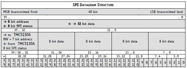
Trinamic TMC5130 is steeper motor driver IC(Datasheet). It has a SPI interfacing with host CPU. My Host controller is PIC18F26K80, an 8 bit PIC microcontroller(Complete knowledge about microcontroller: http://www.apogeeweb.net/article/58.html ). TMC5130 accept 40 bit data over SPI for read/write registers. 40 bit contain 1 write/read bit,7 address bit,32 bit data. in case of register read MSB is 0 and 32 bit data are dummy.

PIC18F26K80 sends 8 bit data at once, so I need to send 5 bytes continuously to TMC5130 to make him understand the data. The issue is, I'm not getting desired data from the TMC5130, motor is not pinning back and forth as it supposed to. PIC26K80 Debug serial Log are as below:
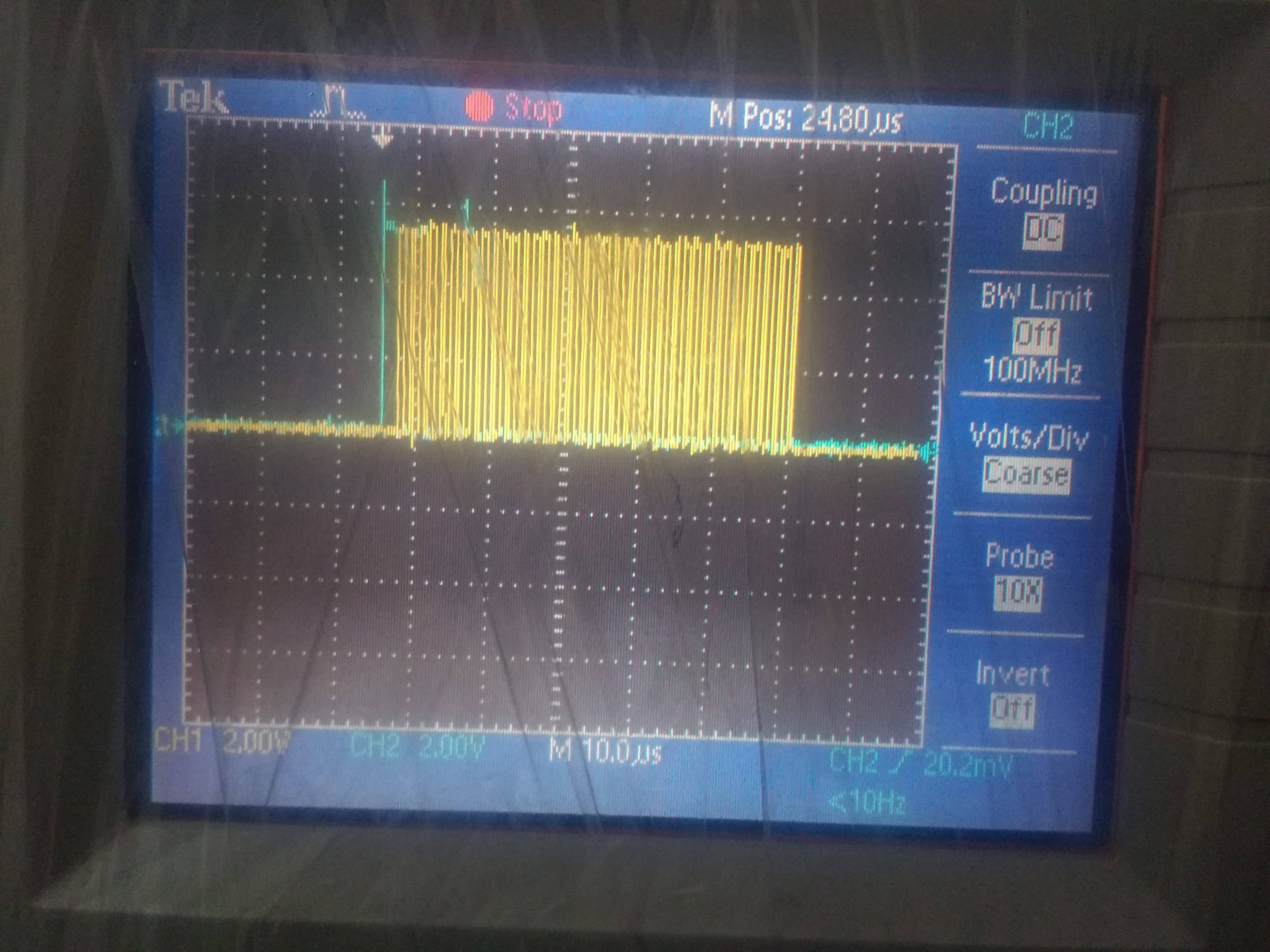
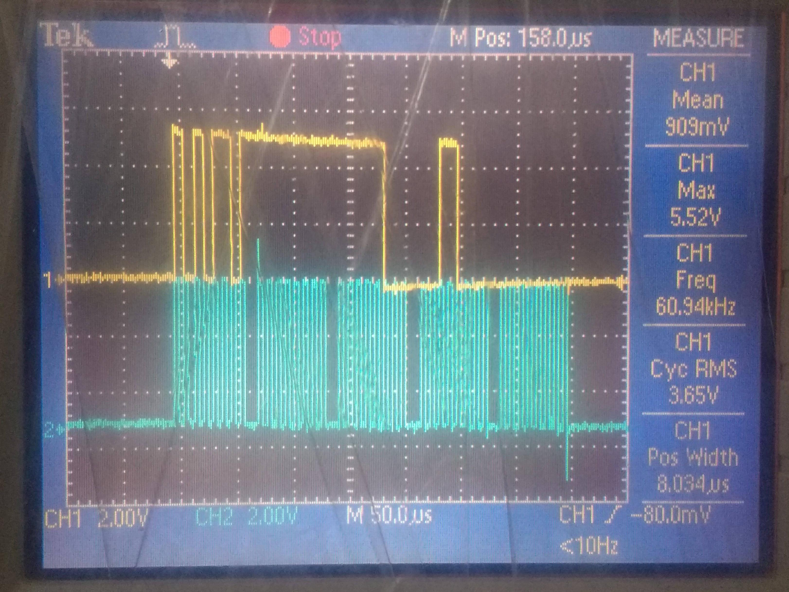
I have captured SPI Clock/Data signals of PIC18F26K80, I'm getting proper data and clock as desired. I have tested TMC5130 with Cypress board, CY8CKIT-042 with same referenced code, its working good as expected. I have captured Clock signals of Cypress as well. I found difference in both SPI-Clock, PIC and Cypress. PIC18F26K80 SPI clock is not continuous where Cypress gives 40 bit clock signal continuously.PIC transmit one byte after another with some micro seconds delay.


So my observation says that there is an issue because of clock only. I need to send 40 bit SPI clock continuously to make TMC5130 understand the command. Now question is How Can I achieve Continuous SPI Master Clock from PIC SPI? I need to confirm that Am I on right direction or not? Can someone here Guide me? Any little help or hint is appreciated. Thanks in Advance.

PIC18F26K80 sends 8 bit data at once, so I need to send 5 bytes continuously to TMC5130 to make him understand the data. The issue is, I'm not getting desired data from the TMC5130, motor is not pinning back and forth as it supposed to. PIC26K80 Debug serial Log are as below:
SPI MASTER Initialize....Received: 0x0000000000PIC18F26K80 SPI Initialization code:
from register: 0x00
Received: 0x7900000000
from register: 0x6C
Received: 0x7900000000
from register: 0x10
Received: 0xF900038301
from register: 0x11
Received: 0xF981000005
from register: 0x70
Received: 0x7905000000
from register: 0x24
Received: 0x7900000000
from register: 0x25
Received: 0x7900000000
from register: 0x26
Received: 0x7900000000
from register: 0x27
Received: 0x7900000000
from register: 0x2A
Received: 0x7900000000
from register: 0x2B
Received: 0x7900000000
from register: 0x20
Received: 0x7900000000
from register: 0x2D
10 Rotation 512000 pulse
Received: 0x7900000000
from register: 0x2D
Received: 0x7900000000
from register: 0x21
STOP
Received: 0x7900000000
from register: 0x21
Received: 0x7900000000
from register: 0x2B
void SPI_Initialize(void) {
    // Set the SPI module to the options selected in the User Interface

    //R_nW write_noTX;
    //P stopbit_notdetected;
    //S startbit_notdetected;
    //BF RCinprocess_TXcomplete;
    //SMP middle of data output time;
    //UA dontupdate;
    //CKE: Transmit occurs on transition from Idle to active clock state;
    //D_nA lastbyte_address;
    //0000 000
    SSPSTAT = 0x00;


    //WCOL no_collision;
    //SSPOV no_overflow;
    //SSPEN enabled;
    //CKP Idle:Low,Active:High;

    //0000 0010
    //(SSPM3:0)---> 0010 SPI Master mode: clock = FOSC/64

    SSPCON1 = 0x02;

    // SSPADD 0;
    //SSPADD = 0x00;
}
PIC18F26K80 SPI I/O Initialization//RB0 as slave1 select outputSPI Byte Exchange from PIC18F26K80 MASTER
//RB1 Drive Enable output for TMC3150
LATB = 0x00;
TRISB = 0xFC;//1111 1100
//WPUB = 0x00;//
//SPI MASTER Mode
//SD0(RC5) as Output
//SCK(RC3) as Outpur
PORTC = 0x00; //0000 0000
TRISC = 0xD4; //1101 0100
uint8_t SPI_Exchange8bit(uint8_t data) {
    // Clear the Write Collision flag, to allow writing
    SSPCON1bits.WCOL = 0;

    SSPBUF = data;

    while (SSPSTATbits.BF == SPI_RX_IN_PROGRESS) {
    }

    return (SSPBUF);
}
SPI Datagram sent from PIC18F26K80 to TMC5130void TMC5130_SendData(unsigned long address, unsigned long datagram) {
Delay_ms(100);
uint8_t stat;
unsigned long i_datagram;
//digitalWrite(chipCS,LOW);
CS1_SetLow();
__delay_ms(10);
stat = SPI_Exchange8bit((address | 0x80));
i_datagram |= SPI_Exchange8bit((datagram >> 24) & 0xff);
i_datagram <<= 8;
i_datagram |= SPI_Exchange8bit((datagram >> 16) & 0xff);
i_datagram <<= 8;
i_datagram |= SPI_Exchange8bit((datagram >> 8) & 0xff);
i_datagram <<= 8;
i_datagram |= SPI_Exchange8bit((datagram) & 0xff);
//digitalWrite(chipCS,HIGH);
CS1_SetHigh();
#ifdef DEBUD_LOG
USARTWriteString("Received: ");
PrintHex40(stat, i_datagram);
USARTGotoNewLine();
USARTWriteString(" from register: 0x");
USARTPrintHex(address);
USARTGotoNewLine();
#endif
}
PIC18F26K80 Code for TMC5130 is referenced from How to drive a stepper motor with your Arduino Mega using a TMC5130-EVALI have captured SPI Clock/Data signals of PIC18F26K80, I'm getting proper data and clock as desired. I have tested TMC5130 with Cypress board, CY8CKIT-042 with same referenced code, its working good as expected. I have captured Clock signals of Cypress as well. I found difference in both SPI-Clock, PIC and Cypress. PIC18F26K80 SPI clock is not continuous where Cypress gives 40 bit clock signal continuously.PIC transmit one byte after another with some micro seconds delay.


So my observation says that there is an issue because of clock only. I need to send 40 bit SPI clock continuously to make TMC5130 understand the command. Now question is How Can I achieve Continuous SPI Master Clock from PIC SPI? I need to confirm that Am I on right direction or not? Can someone here Guide me? Any little help or hint is appreciated. Thanks in Advance.